Most of my blog posts derive not from what I think you ought to know about Cisco UCS although some certainly do, but generally from customer questions about the technology, and if one customer is asking a particular question then likely many customers will be asking the same question and this one’s a cracker!
A customer said to me the other day something like:
“Our current Blade infrastructure meets our security standards, where we CANNOT have traffic separated solely by VLANs, it does this by using separate modules in the Chassis to which we run separate cables, and we are unclear if Cisco UCS will give us the same level of traffic separation”
Great question, Hold tight let’s go!
OK, what we are really talking about here is the physical architecture of Cisco UCS, so for the purposes of providing some context to the discussion let’s assume we have two bare metal Windows blades which sit of different VLANs and those VLANs for whatever reason cannot co-exist on any NIC, cable or switch if the only separation between them would by VLAN ID (802.1Q Tags). I chose bare metal blades because there is already a myriad of ways for providing secure separation between Virtual Machines in the same Cisco UCS Pod, utilising Cisco Nexus 1000v and Virtual Secure Gateway (VSG) to name but one.
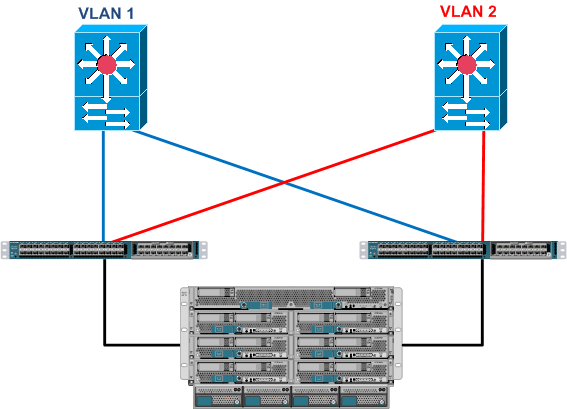
So first off these VLANs start off life in the network Core either on separate physical switches or on the same switch but separated by Nexus Virtual Device Contexts (VDC) or Virtual Routing and Forwarding (VRF), but let’s keep it simple and assume these VLANs exist on physically separate upstream switches, which in turn are connected in to our Cisco UCS Fabric Interconnects.
So first thing to remember is that while the Cisco UCS Fabric Interconnect my look like a Cisco Nexus 5k that has simply been painted a different colour 🙂 it doesn’t act like one.
I’m sure you are aware of the traditional Switch Mode Vs End Host Mode “debate” but this never really crops up anymore since version 2.0 code and the support for disjointed layer 2 domains. Of which the above diagram is a prime example.
As I’m sure you know the Fabric Interconnects by default run in End Host Mode, in which they appear to the upstream LAN and SAN as just a huge server with multiple NICs and HBA’s. And as we also know with Cisco UCS what you see is certainly not what you get, what I mean by that is the server, the NIC, the cable and the switch port are all virtualised.
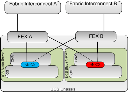
So let’s take our two servers, the server in slot 5 will be in VLAN 1 (blue) and the server in slot 6 in VLAN 2 (red)
So again for the sake of simplicity we will only use a single FEX to FI cable and create a single vNIC on each server mapped to Fabric A with the redundancy provided by hardware fabric failover.
So logically the setup is as per the below.
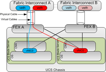
OK the next key concept to understand is that whenever you create a vNIC on a Cisco CNA like the Virtual Interface Card (VIC) this automatically creates the corresponding virtual Ethernet port on the fabric interconnects (On both FI’s if fabric failover is enabled) and connects the veth to the vNIC with a virtual cable as shown below, this creates a Virtual Network Link (VN-Link).
This is because the Cisco VIC is a Fabric Extender in mezzanine form factor. This is known as Adapter FEX.
Next key concept: The cable between the FEX and the Fabric Interconnect is not a standard 802.1Q trunk, as with all FEX technologies you can think of these cables as “The Backplane” connecting the Control Plane (FI) to the Data Plane (FEX).
Obviously the FI does need to tag traffic between the FI and the FEX in order to ensure traffic from a particular vNIC is correctly delivered only to its corresponding veth but these tags are not 802.1Q tags but instead Virtual Network TAGs (VN-TAGs) which are applied in hardware and as such much harder to Spoof
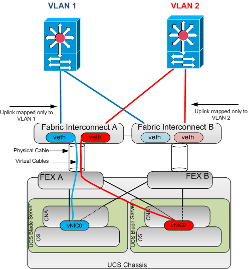
So the end to end picture looks like this.
So as you can see if we have a vNIC which only carries a single VLAN and that VLAN is defined as native, then there is no 802.1Q tags required. And similarly with regards to the uplinks if they are only mapped to a single native VLAN again no 802.1Q tags are required on these links.
So logically the above setup is the same architecture as having a server with 2 physically separate NICs connected into different upstream networks. Which if you remember complies with the customers security requirements.
As always comments welcome.


IMO the customer in question did not provide sufficient detail regarding their security policy. They really need to explain which attack vector(s) need to be taken care of, when they are talking about VLANs.
In case of UCS, for example, there is a potential for an operator error or malicious modification of the UCS configuration, which could lead to misdirected traffic. For some other, less integrated blade systems, it is possible to come up with a hardware configuration which will eliminate this possibility entirely.
Just my 2c.
Thanks for the comment Dimitri, and agree There is potential for Admin misconfigurations but I think you have to trust that your Admins know what they are doing, even in a physically seperate blade architecture user errors can cause possible compromises i.e. is it really any different a UCS admin assigning a NIC to an incorrect VLAN than an engineer getting confused and plugging a wrong cable into the wrong module in a different blade architecture. Reality is these “misconfigs” are usually picked up pretty quickly as what you are trying to achieve usually doesn’t work if you are not in the correct VLAN for you IP address for example.
And re malicious mods, again we all have to trust in somebody , but standard good security practices like RBAC, backups, AAA and revoking access to terminated employees promptly etc.. all help.
Appreciate the comments.
Colin
Awesome post, this is exactly how I plan on implementing UCS traffic separation for the DMZ and this confirms my ideas. Unfortunately I don’t have the luxury of the nexus 1000v so have VSG available in my design 😦
In so
Thanks
Tom
Hi Tom
Thanks for the comments.
N1KV and VSG certainly give you a lot of options for VM seperation on the same dvS, without them and just using standard vSwitches configuring multiple VNTAG seprarted vNICs uplinks each connected to a different vSwitch would be the way to go, as per the example in the post. For DMZ implementations if there is no East/West communication between DMZ hosts, private VLANs are also a good option.
Colin
thanks for the great post!, I have this question how fex in the above diagram does bifurcation of traffic coming from different vnics of various blade servers !
Hi Inder
Firstly I just had to go an lookup what “bifurcation” meant, but now I know it means to split into 2 parts, I’m thinking your question is around how does the FEX cope with seperating the traffic from different vNICs.
The Answer is via applying virtual network tags (VN-TAGs) i.e. a vNIC is tied to a vEth via a virtual cable (this relationship is called the virtual network link (VN-LINK) when ever traffic egresses a vNIC the appropriate VN-TAG is applied to ensure it is delivered to the correct vEth, the same is true of traffic comming into the FI, the destination MAC is looked up and the relevant vEth is discovered and the VN-TAG is applied and sent to the FEX for delivery to the correct vNIC.
Regards
Colin
Thank you so much! I almost forgot it after asking question..
In this design above which network element (mezzanine adapter or FEX or FI ) is applying the dot1q tagging .
Ullas
Hi Ullas
In UCS Archiecture there is no concept of an “Access Port” All UCS ports virtual and physical are Trunk Ports, if they are set to only carry a single VLAN and that VLAN is native the port is still in Trunk Mode but only carrying that single VLAN.
So in answer to your question .1q Tags are appplied/removed by the vNICs and the FI Physical uplink ports. The FEX’s are in the middle of the exchange and do not apply/remove .1q tags but instead use VNTAGs (802.1BR) which are applied/removed by the controlling bridge (Which in the case of UCS is the Fabric Interconnect).
Regards
Colin
Why we don’t keep same Vlan I’d and Vsan Id same what is the conflict both are different technology
Hi
It is fine to Have VSAN ID’s that happen to be the same number as a VLAN ID.
I think you may be getting confused with VLAN ID and FCoE VLAN ID’s
VLANs in the LAN cloud and FCoE VLANs in the SAN cloud must have different IDs. Using the same ID for a VLAN and an FCoE VLAN in a VSAN results in a critical fault and traffic disruption for all vNICs and uplink ports using that VLAN. Ethernet traffic is dropped on any VLAN which has an ID that overlaps with an FCoE VLAN ID
Regards
Colin
Thanks a lot for the reply , i got the point
So let’s pretend I have a set up where I have two DMZ’s each one is physically isolated on a catalyst 3750 but due to short sighted administrators from the past each 3750 is utilizing VLAN 1. I see what you said there’s no such thing as an access port inside UCS so does that mean that I have to trunk from the 3750s into the interconnects? Or can I leave the 3750s as access ports?
Yes you can, to get the equivalent of an access port in Cisco UCS, just tag the VLAN you want and set it as Native.
Regards
Colin
Will this level of separation sufficient for using a single UCS chassis for servers in DMZ and Internal network? Do you suggest such a configuration with Disjoint L2 VLAN configuration?
Hi Ram
With my Security hat on I would say No, DMZ should be “Air Gap” seperated from an internal Network with physically seperate kit (or a VDC if you use N7K). and a Stateful Firewall between them,
That said itm comes down to your own security policy.
You could certainly seperate the DMZ and Internal Networks within the UCS and have a Physical / Virtual FW provide the seperation, but again user misconfigurations could comprimise the speration.
And yes this setup works just fine for Disjoint L2.
Regards
Colin
Hi Colin,
I would like to know how i will trace the particular VLAN traffic on a particular vNIC of a blade and also i have port channel in my environment how to see a particular vlan traffic going via which uplink