
As promised here is the 2nd part of the Unified Fabric post, where we get under the covers with FCoE.
The first and most important thing to clarify is as its name suggests Fibre Channel over Ethernet (FCoE) still uses the Fibre Channel protocol, and as such all the higher level processes that needed to happen in a Native Fibre Channel environment FLOGI/PLOGI etc., still need to happen in an FCoE environment.
So having a good understanding of Native Fibre Channel operations is key. So let’s start with a quick Native Fibre Channel recap:
For the IP Networker I have put some parentheses () and corresponding IP services that can be very loosely mapped to the Fibre Channel process to aid understanding.
Native Fibre Channel
Initiators/Targets contain Host Bus Adapters (HBA’s) which in Fibre Channel terms are referred to as Node ports (N ports).
These N Ports are connected to Fabric Ports (F ports) on the Fibre Channel switches.
Fibre Channel switches are then in turn connected together via Expansion (E) Ports, or if both Switches are Cisco you have the option of also Trunking multiple Virtual SANs (VSANs) over the E ports in which case they become Trunking Expansion Ports (TE Ports).
First the initiator (server) sends out a Fabric Login (FLOGI) to the well-known address FFFFFE, this FLOGI registers the unique 64bit World Wide Port Name (WWPN) of the HBA (Think MAC Address) with the Fibre Channel Name Server (FCNS).
The FCNS is a service that automatically runs on an elected “Principal switch” within the Fabric. By default the switch with the lowest Domain ID in the Fabric is elected the Principal Switch.
The Principal Switch is also in charge of issuing the Domain ID’s to all the other switches in the Fabric.
The FCNS then sends the initiator back a unique 24bit routable Fibre Channel Identifier (FC_ID) also referred to as an N_Port_ID (Think IP Address) the 24bit FC_ID is expressed as 6 Hexadecimal digits.
So the basic FLOGI conversation goes something like “Here’s my unique burned in address” send me my routable address (think DHCP)
The 24bit FC_ID is made up of 3 parts:
• The Domain ID, which is assigned by the Principal switch to the Fibre Channel switch, to which the host connects.
• The Area ID, which actually is the port number of the switch the HBA is connected to.
• The Port ID which refers to the single port address on the actual host HBA.
The above format ensures FC_ID uniqueness within the fabric.
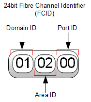
Figure 1 Fibre Channel Identifier
Once the initiator receives its FC_ID, it then sends a Port Login (PLOGI) to well-known address FFFFFC which registers its WWPN and assigned FC_ID with the Fibre Channel Name Server (FCNS). (Think of the FCNS Server like DNS). The FCNS then returns all the FCID’s of the Targets the initiator has been allowed to access via the Zoning policy.
Once the PLOGI is completed, the initiator starts a discovery process, to find the Logical Unit Numbers (LUNs) it has access to.
The FLOGI database is locally significant to the switch and only shows WWPN’s and FC_ID’s of directly attached Initiators/Targets, the FCNS database on the other hand is distributed across all switches in the fabric, and shows all reachable WWPN’s and FC_ID’s within the Fabric.
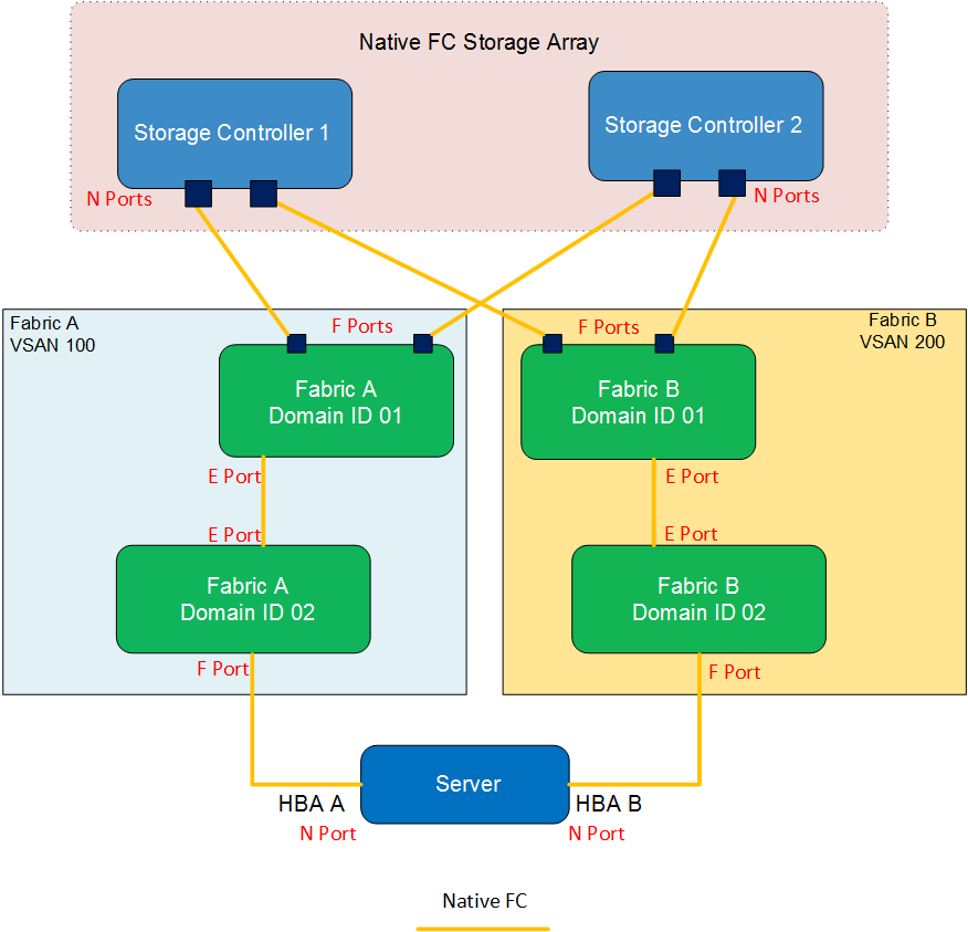
Figure 2 Native Fibre Channel Topology.
OK History lesson over.
The Fibre Channel protocol has long proven to be the best choice for block based storage (storage that appears as locally connected), and FCoE simply takes all that tried and tested Fibre Channel performance and stability, and offers an alternative layer one physical transport in this case Ethernet.
But replacing the Fibre Channel transport, did come with its challenges, The Fibre Channel physical layer creates a “lossless” medium by using buffer credits; think of a line of people passing boxes down the line, and if the next person does not have empty hands (available buffer), they cannot receive the next box, so the flow is “paused” until the box can again be passed.
Ethernet on the other hand expects drops and uses windowing by upper layer protocols in order to not over whelm the receiver, instead of a line of people passing a box from hand to hand, think of a conveyor belt with someone just loading boxes on it, at an ever increasing speed, until they hear shouts from the other end that boxes are falling off, at which point they slow their loading rate and gradually speed up again.
So the million dollar question was how to send a “lossless” payload over a “lossy” transport.
The answer to which, was several enhancements to the Ethernet Standard generally and collectively referred to as Data Centre Bridging (DCB)
Fibre Channel over Ethernet
OK so now we have had a quick refresher on Native Fibre Channel, let’s walk through the same process, in the converged world.
First of all let’s get some terminology out of the way,
End Node (E-Node) the End host in an FCoE network, containing the Converged Network Adapter (CNA) this could be a Server or FCoE attached Storage Array.
Fibre Channel Forwarder (FCF) Switches that understand both Ethernet and Fibre Channel protocol stacks.
NB) An FCF is required whenever FC encapsulation/de-encapsulation is required. But as an FCoE frame is a legal tagged Ethernet frame it could be transparently forwarded over standard Ethernet switches.
The next thing to keep in mind is that Fibre Channel and Ethernet work very differently, Ethernet is an open mulit-access medium, meaning that multiple devices can exist on the same segment and can all talk to each other without any additional configuration.
Fibre Channel on the other hand is a closed point to point medium , meaning that there should only ever be point to point links, and hosts by default cannot communicate with each other, without additional configuration called Zoning (Think Access Control List).
So if you keep in mind that in an FCoE environment we are creating 2 separate logical point to point Fibre Channel Fabrics (A&B) just like you have in a native Fibre Channel environment, you should be in pretty good shape to understand what config is required.
So as explained in the Native Fibre Channel refresher above, an N Port in a Host, connects to an F port in a switch and then that switch connects to another Switch via an E port, similarly in the FCoE world we have a Virtual N Port (VN_Port) which connects to a Vitrual F Port (VF_Port) in the FCF and then if two FCF’s need to be connected together this is done with Virtual E (VE_Ports).
As can also be seen in the below figure, as the FCF is fully conversant in both Ethernet and Fibre Channel as long as they have native FC ports configured they can quite happily have native FC initiators and Targets connected to them.

Figure 3: Multi-Hop Fibre Channel over Ethernet Topology
So as can be seen above an FCoE Network is a collection of virtual Fibre Channel links, carried over and mapped onto an Ethernet Transport, but what makes the logical links between the VN_Ports, VF_Ports and VE_Ports? Well a few control protocols are required, collectively known as FCoE Initialisation Protocol (FIP) and it is FIP which enables the discovery and correct formation of these virtual FC links.
Under each physical FCoE Ethernet port of the FCF a virtual Fibre Channel Port (vfc) is created, and it is the responsibility of FIP to identify and create the virtual FC link.
Each virtual FC link is identified by 3 values the MAC addresses at either end of the virtual circuit and the FCoE VLAN ID which carries the encapsulated traffic.
Every FC encapsulated packet must use a VLAN ID dedicated and mapped to that particular VSAN. No IP data traffic can co-exist on a VLAN designated on the Nexus switch as an FCoE VLAN. If multiple VSANs are in use, a separate FCoE VLAN is required for each VSAN.
As we know Ethernet has no inherent loss prevention mechanisms, therefore an additional protocol was required in order to prevent any loss of Fibre Channel packets traversing the Ethernet Links in the event of congestion. A sub protocol of the Data Centre Bridging standard called Priority Flow Control (PFC) IEEE 802.1Qbb ensures zero packet loss by providing a link level flow control mechanism that can be controlled independently for each frame priority. Along with Enhanced Transmission Selection (ETS) IEEE 802.1Qaz which enables the consistent management of QoS at the network level by providing consistent scheduling.
Fibre Channel encapsulated frames are marked with an Ethertype of 0x8906 by the CNA and thus can be correctly identified, queued and prioritised by PFC which places them in a prioritised queue with a Class of Service (CoS) value of 3 which is the default for encapsulated FC packets. FIP is identified by the Ethertype of 0x8914.
Before the FIP negotiation can start, the physical link needs to come up, this is a job for the Data Centre Bridging capabilities eXchange (DCBX) protocol, which makes use of the Link Layer Discovery Protocol (LLDP) in order to configure the CNA with the settings (PFC & ETS) as specified on the switch to which the CNA is connected.
FIP can then establish the virtual FC links between VN_Ports and VF_Ports (ENode to FCF), as well as between pairs of VE_Ports (FCF to FCF), since these are the only legal combinations supported by native Fibre Channel fabrics.
Once FIP has established the virtual FC circuit, it identifies the FCoE VLAN in use by the FCF then prompts the initialisation of FLOGI and Fabric Discovery.
The diagram below shows the FIP initialisation process, the green section is FIP which will identified with the Ethertype 0x8914 and the yellow section is FCoE identified with the Ethertype of 0x8906.

It is also worth noting that the E-Node uses different source MAC addresses for FIP and FCoE traffic, FIP traffic is sourced using the burned in address (BIA) of the CNA whereas the FCoE traffic is sourced using a Fabric Provided MAC Address (FPMA).
FPMAs are made up from the 24 bit Fibre Channel ID (FC_ID) assigned to the CNA during the FIP FLOGI process, this 24 bit value is appended to another 24 bit value called the FCoE MAC address prefix (FC-MAP) of which there are 256 predefined values, but as the FC_ID is unique within the fabric itself, Cisco apply a default FC-MAP of 0E-FC-00.

Figure 4 Make-up of the Fabric Provided MAC Address (FPMA)
The fact that FIP and FCoE make use of a tagged FCoE VLAN requires that each Ethernet port configured on the FCF is configured as a Trunk port, carrying the FCoE VLAN. Along with any required Ethernet VLANs. If the Server only requires a single VLAN, then this VLAN should be configured as the Native VLAN on the physical Ethernet port to which the ENode connects.
Ok, it would only be right for me to include a bit on how Cisco UCS fits in to all this.
Well as we know the Cisco UCS Fabric Interconnect by default is in End Host Mode for the Ethernet side of things and in N-Port Virtualisation (NPV) mode for the storage side of things.
This basically means the Fabric Interconnect appears to the servers as a LAN and SAN switch, but appears to the upstream LAN and SAN switches as just a big server with lots of HBA’s and NICs inside.
There are many reasons why these are the default values, but the main reasons are around scale, simplicity and safety. On the LAN side having the FI in EHM prevents the possibility of bridging loops forming between the FI and upstream LAN switch, And in the case of the SAN, as each FI is pretending to be a Host, the FI does not need a Fibre Channel Domain ID, neither does it need to participate in all the Fibre Channel Domain Services.
As can be seen from the below Figure in the default NPV mode the Cisco UCS Fabric Interconnect is basically just a proxy. Its server facing ports are Proxy F ports and its Fabric facing (uplink) ports are Proxy N ports.
Again note no FC Domain ID is required on the Fabric Interconnects.
Also that as we are using Unified Uplinks from the FI to the Nexus (FCF), we cannot use Virtual Port-Channels to carry the FCoE VLAN, as the FCoE VLAN and corresponding VSAN should only exist on a single Fabric. We could of course create an Ethernet Only vPC and then have a separate Unified Uplink carrying the FCoE VLAN to the local upstream Nexus, but if you’re going to do that, you may as well just have stuck with a vPC and Native Fibre Channel combo.
As would be the case with any multi-VSAN host, the Cisco Nexus ports which are connected to the UCS FI are configured as Trunking F (TF) ports.
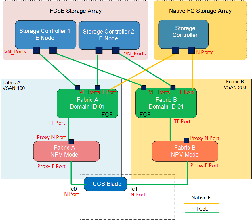
Figure 5 FCoE with Cisco UCS Unified Uplinks.
Well hope you found this post useful, I’ll certainly be back referencing it myself during the Storage elements of my CCIE Data Center studies, as it is certainly useful having all elements of a multi-hop FCoE environment, along with the Native Fibre Channel processes all in a single post.
Until next time.
Colin

Hi Colin,
Nicely done. One minor (and I do mean minor) nit:
The FIP protocol does not create node types. VN_Ports, VE_Ports, VF_Ports are handled either manually (during switch configuration setup) or pre-configured by vendors (as in the case of CNA and storage controller vendors). FIP itself uses the well-known MAC address of the FCF to learn the appropriate FCoE VLAN to choose, and does not generate any addresses on its own.
While it’s a minor clarification, I do think it could have unintended consequences for those that think that FCoE has a built-in autodiscovery and end-to-end configuration negotiation through FIP, which isn’t the case.
Otherwise, great post. 🙂
Best,
J
Thanks for the Clarification J 🙂 I’ll make that section a little clearer.
Nice post Colin. My only comment is on this statement:
“We could of course create an Ethernet Only vPC and then have a separate Unified Uplink carrying the FCoE VLAN to the local upstream Nexus, but if you’re going to do that, you may as well just have stuck with a vPC and Native Fibre Channel combo.”
Most of the current FlexPod designs utilize exactly this, vPC between FI and 5K for IP based storage and normal data traffic, along with a dedicated (not Unified), seperate FCoE uplink.
Did I understand your point correctly? I suspect not, as I know you are well involved with FlexPod and would know the CVDs as well.
Indeed Adam, in fact I did a design just like that recently.
FlexPods a great solution!
Thanks for the comment.
Colin
Colin,
As FC frames coming out of vHBAs are encapsulated to FCoE frames at the I/O module, I would like to know what the source and destination mac look like in the FCOE frame. If these are FPMAs, is there a way to view them in UCSM?