
If you have ever wanted a sneaky peak under the UCS Kimono (GUI) then this posts for you.
The goal of this post is to clarify the end-to-end path from a Cisco UCS vNIC through the UCS Infrastructure to the point we egress from the Cisco UCS Fabric Interconnects.
Having this information and being able to check utilization and statistics of all virtual and physical interfaces within the Cisco UCS environment will save you allot of time and give you a much better understanding of how all the elements tie together.
This post builds on from a previous post “Understanding UCS VIF Paths” where we used a combination of the GUI and CLI to establish the end-to-end traffic path used by a vNIC/vHBA. In this post we exclusively use the CLI, so if you haven’t done so already perhaps worth checking the previous post out first.
https://ucsguru.com/2012/05/18/understanding-ucs-vif-paths/
Anyway I was troubleshooting an intermittent performance issue the other day from a Cisco UCS Blade all the way back to the Storage Array. And thought it would make a useful post to document this part of the process.
And certainly if you ever get as far as needing to open a Service Request (SR) with Cisco, being able to provide the below information will save you and TAC allot of time.
During this process I will be attaching directly to the ASICs within the IO Modules and these ASICs differ depending on whether you are using Generation 1 or Generation 2 Hardware.
As a nice “Cheat Sheet” I have provided the below table and graphic to show the relevant Cisco UCS ASIC and code names some of which we will need for this process.

UCS ASICs
In this example we will confirm the end-to-end path of a vNIC named vNIC_FabB1 of Service Profile DCN4PBKW001 which is in Chassis 3 Slot 2
First determine the Virtual Interface (VIF) and Which Fabric the vNIC/vHBA is currently using (If Fabric Failover is enabled)
Command “show service-profile circuit server <Chassis #>/ <Slot #>”

Active Fabric and Assigned VIF
As we can see vNIC_FabB1 is Active and Primary on Fabric B and Passive and Standby on Fabric A. Therefore we can determine that the Active Fabric for this vNIC is Fabric B.
We can also see that the VIF associated with this vNIC is VIF 2024.
SideNote) This vNIC will connect via a Virtual Network Link (VN-LINK) to a vEth port of the same name vEth2024 on Fabric Interconnect B which can be viewed and statistics collected via the Connect NXOS command at the UCSM CLI.
The next thing to determine is which internal IOM (FEX) Port VIF 2014 is using.
From the UCSM CLI
Connect iom <Chassis #>
Show platform software woodside sts (use “redwood” for IOM 2104)

FEX Diagram
I love the above command because it shows a representation of exactly how the FEX is being used. You can see all the Internal Blade Facing “Satelitte” ports or Host Interfaces (HIFs) and all the External FEX Network Ports or (NIFs).
As can be seen Blade 2 has access to internal FEX ports 3&4 but has only one active connection to the FEX on FEX Port 3, which maps to HIF 27 (Outlined in Red)
NB) The reason FEX Port 4 is disabled, is that the ports of a 220x FEX alternate between the mLOMs and the Mezzanine slots of the Blades, the Mezzanine slots in the above example being empty (hence all alternate (even) ports display as “–“ for Disabled)
Now we know which Host Interface (HIF) we are using, we next need to determine which FEX Network Interface (NIF) is being used.
If you are using a Port-Channel between the FEX and the FI all servers will be mapped to the port-channel and distributed over the members by the LACP algorithm.
In this case the FEX Links have been left at the default setting which is “Discrete Pinning” mode and as such then the relationship between server slot and FEX Network Interface is as follows:
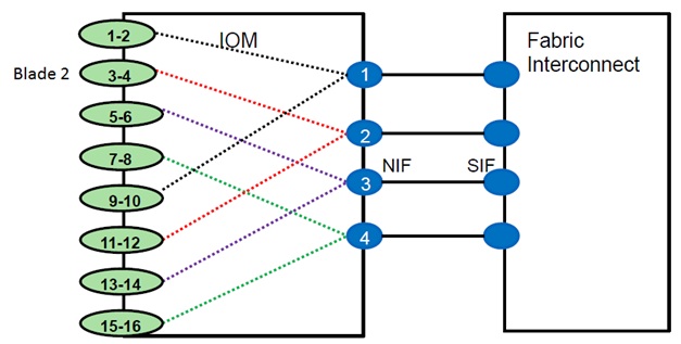
HIF to NIF Mapping (4 FEX Links)
So as can be seen above FEX Port 3 maps to Network Interface 2.
The HIF to NIF mapping differs depending on the IOM used and how many FEX cables are actually connected, the above shows all four links of a 2204XP connected, the below example shows how the HIF to NIF mapping occurs if 2 FEX Cables are used:
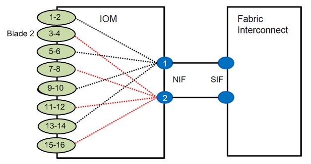
HIF to NIF Mapping (2 FEX Ports used)
So Blade 2 (FEX Ports 3 &4) maps to Network interface (NIF 2)
OK so next we establish which Server Interface (SIF) on the Fabric Interconnect we are using , which we do with the below command:
Show fex <Chassis #> detail
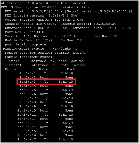
FEX Port to Fabric Interconnect Server Port Mapping
So as you can see FEX Port E3/1/3 is using FI Fabric Port Eth1/10
The last port we need to know is which FI Uplink port we are pinned to
Show pinning server-interfaces | inc Veth2024

vEth to Uplink Port Pinning
NB) show pinning border-interfaces active can also be used to see the information from another perspective.
As you can see Veth 2024 is pinned to FI Uplink Port-Channel 11
So armed with all the above information you can draw out all the ports in the Cisco UCS traffic path. This in itself will save a lot of time if you need to engage TAC.
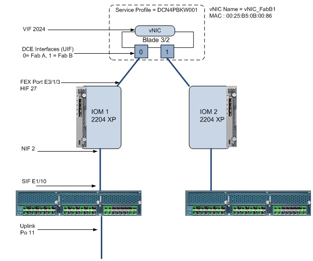
End-to-End Traffic Path within the UCS Infrastructure
Have Fun!
NB) For further information on advanced Cisco UCS Troubleshooting at the CLI I would strongly suggest checking out the recorded session by Robert Burns (First CCIE DC, TAC and Cisco Community Legend) available for free at https://www.ciscolive.com just set up an account.
BRKCOM-3002 – UCS Performance Troubleshooting
https://www.ciscolive.com/online/connect/sessionDetail.ww?SESSION_ID=8196&tclass=popup

Pingback: End of year Randomness | speakvirtual
I noticed in your “FEX Port to Fabric Interconnect Server Port Mapping” image you show 17 HIFs when I would have expected 16. I ran the same command as well on my 2280’s and saw 33 HIFs. If I do a “sh int eth 1/1/33″ it displays ” Hardware: 1000 Ethernet” as opposed to the other 32 ports that display “Hardware: 10000 Ethernet.” I am guessing this is some sort of management port maybe for CIMC? I am just guessing. Do you happen to know?
Hi Steve
Yes there is a “Hidden” extra port on the FEX which connects through to the Chassis Management Controller (CMC) inside the FEX which is the internal network which the CIMCs connect into.
Regards
Colin
Reblogged this on SIPALOOZA.
Hi Colin,
Thanks for the details.
Just want to know if there is any relation between the HIF any the FEX back panel ports . IN you other post on “Understanding UCS VIF Paths” you mentioned “Internal Server facing ports (Sometimes referred to as Host Interfaces (HIFs))” but here in this post i can see that HIF & the internal fex ports are different.
Pingback: Traffic Load Balancing in Cisco UCS | Niktips's Blog